Economical and free Microsoft Excel, Mathsoft MathCAD & Microsoft Word templates spefically designed to save you time and money. 

Hawaii Marine Templates Banner Pics
Hawaii Marine Templates
45-302 Makalani Street,
Kaneohe, HI, USA   96744-2819

Phone (808) 291-0348 
Fax (808) 247-6443
website: www.hawaii-marine.com/templates
email: bt@hawaii-marine.com
Hawaii Marine Company - naval architecture, boat & yacht design,  marine engineering, maritime expert witness, marine photography, NAVIC 10-92 submittals, nautical systems, professional engineer, stability tests, computer aided design and drafting services Those involved with nautical and professional engineering sectors can benefit from these products.  Products are suitable for use by Naval Architects, Marine, Ocean, Nautical, Structural, Civil & Mechanical Engineers, Sailors, Ship, Yacht & Boat Designers, Vessel Owners & Operators, Boat Builders, Construction Contractors and others.
Home Page | Background | References | Stability Article | Trim Article | Barge Trim & Stability Article 
Composite EAM Article | Equivalent Area Method Example | Usage Terms | Privacy Policy | Tech Support
F. A. Q. | User Remarks | Resource Links | Related Links | Sail Boat Books | Nautical Books

Waterplane Sheet (English Units)

Description: 
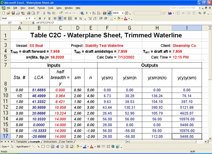
For a given input waterline this spreadsheet computes hydrostatic waterplane area characteristics relating to station half beam inputs.  Basically it sums the area under a half beam (or waterline) curve to obtain the waterplane area, it takes moments to obtain the longitudinal  center of floatation and computes moments of inertia in both the transverse and longitudinal directions. 
     If the input waterline is level, the data obtained may be used as an input source for a vessel's "Curves of Form."  Inputs are based on a Lines Drawing with ten stations starting at zero and ending at Station Ten.  This Lines Drawing has customary half stations at each end to compensate for vessel fineness.  The numerical integrations contained in these calculations are based on Simpson's Rules.
     Though optional, this spreadsheet is best utilized in conjunction with a Displacement Sheet (Product Disp-e) and Waterline Input/Output Sheet (Product WL-IO-e).  A further enhancement is dynamically combining this sheet along with a Displacement Sheet and a Waterline Input/Output Sheet.  The product that combines all these sheets together is called a Waterline Hydrostatics Data Sheet (Product WL-hydro-e).  This later enhanced combination facilitates faster and easier computation for a given waterline.  In the combined case, calculations are more automated, significantly minimizing the data entry input time.

Electronic Document Type:  Microsoft Excel spreadsheet           Cost: $10.00 US funds

Number of Pages: Includes an template (or input) sheet, along with an example sheet, an instructions sheet and a use terms sheet.                   

Inputs:  

  • The following dimensional and property input data are required:

    • Clearly document the WL condition being evaluated.  Enter the forward draft (TFWD), midships draft (TMID), aft draft (TAFT) and maximum draft (T).

    • Then enter the station spacing (s)

    • Enter in half beams (y) for each station.  Note the vessel must be divided into ten stations (this yields eleven half beams) with a half station at each end (this adds two more half beams).  This means a total of thirteen input cross half beams are required. 

    • For vessel's with overhang; add in the aft overhang waterplane surface area as well as the longitudinal center of area for this surface from Station 5.  The longitudinal and transverse moments of inertia for this overhang area are also required.  This data is often needed because many vessels that end their LBP (in the Lines Drawing) at the center of the rudder post.  This correction compensates for the area that is aft of the rudder post, which may be substantial.

  • Optional Input Items:

    • Vessel name, project description, client and calculation date and time.

Outputs:  

  • The automatic output generated by this spreadsheet are the waterplane area (A), Longitudinal center of floatation (LCF), longitudinal moment of inertia about the LCF (ILCF), and Transverse Moment of Inertia about Centerline (IT).  Note the LCF obtained is the distance from Station 5.

Suggested Reading (see References page for more detail on these items):

  • Microsoft Excel user manuals

  • Principles of Naval Architecture, Edward V. Lewis, SNAME

  • Basic Ship Theory, Rawson & Tupper

  • Applied Naval Architecture, Robert B. Zubaly

  • Introduction to Naval Architecture, E. C. Tupper

  • Introduction to Naval Architecture, Thomas Gillmer and Bruce Johnson

Terms: Prior to purchase, read our End User License Terms.

Important Notice to European Union Buyers: Due to changes in international law, we no longer accept purchases from any individuals located within an EU country.  However, businesses located within the EU are allowed to make purchases, provided that they make the VAT payments for any imported items purchased electronically.  These EU businesses must specify their VAT number in the memo section on the Paypal payment pages.  These changes are effective as of July 1, 2008, and were modified for EU businesses on April 9, 2010.  

Download Now: Click one of the following buttons to pay.  After payment you will be taken directly to the download page.

Minimum System Requirements: Windows 95/98/NT/2000/XP/Vista/Windows7

Sample: A sample document is shown below.