Advanced Sailboat Parameter Calculations & Checks
(English Units)
Description:
This spreadsheet takes you input values for your sail
boat and automatically calculates many of your
sail boat's numerical characteristics (ratios,
coefficients and parameters). Then this spreadsheet presents various
target values allowing you to quickly check and
compare your sailboat's characteristics
with other similar
successful sail boats.
There are several advantages and benefits to this
calculative approach. Some of these advantages are listed below.
-
First this method saves time. Many of computations
are quickly generated behind the scenes on your input data.
Also to modify, simply change a value in the spreadsheet and it will
automatically and immediately recalculates all affected values.
-
Second this approach provides clear and neat
documentation.
-
Third this approach is cost effective because the
calculative approach is already developed for you, research time is
minimized to the familiarization of concepts when necessary and not to
time consuming development activities.
-
Fourth this template is kept simple, it contains no Excel
macros and there is no Visual Basic code utilized in it's creation.
Also advanced Excel features such "Goal Seek," "Solver" and "Scenarios"
are not used.
-
Fifth, because this is a spreadsheet and not a program,
the users can easily modify it to suit their particular needs.
Electronic Document Type: Microsoft Excel
spreadsheet
Cost:
$50 US funds
Organization and Content:
-
Inputs (all inputs marked with an asterisk
*
are affected by the vessel condition under evaluation. This vessel
condition may be light condition, half load or full load condition, or
some other condition. All asterisk values must change when the
vessel condition changes.)
-
Inputs Sheet 1
-
Weight or Displacement, D,
pounds, usually half load condition
*
-
Ballast Weight, pounds, WB,
in keel and in hull.
-
Draft, Waterline Draft, feet, from waterline to
bottom of keel
*
-
Draftc,
Canoe Draft, feet, from waterline to bottom of hull
*
-
Length Over All, LOA, feet (includes spars, bow
pulpits etc.)
-
Length of Hull, L, LOH or LOD (for older
vessels), feet (length of hull's watertight envelope stem to stern.
This does not include spars, bow pulpits, swim-steps etc., Length on
Deck is the same value, except for vessels with reverse transoms, in
which case the length is extended to the bottom end of the transom)
-
Length of Waterline, LWL, feet
*
-
Hull Beam, Maximum, Bmax,
feet (for hull only, does not include rub rails, fenders, etc.)
-
Maximum Waterline Beam, BWL, feet
*
(this value can be estimated, where BWL = 0.9 x Bmax)
-
Freeboard Forward, FFWD,
feet*,
waterline to top of hull forward
-
Freeboard Aft, FAFT,
feet*,
waterline to top of hull aft
-
Length of Waterline, LWL, feet
*
-
Maximum Cross Sectional Area, Amax,
square feet*
(maximum cross sectional area below the waterline, this value may be
found on a sectional area curved for the condition under evaluation)
-
Sail Area, SA, square feet,
(total sail area which includes all the fore-triangle, the main, and
other normal sails present {like half the area of mizzens on ketches
and yawls and all the foresail area on schooners}. It does not
include stay sails nor does it include spinnakers and jibs in the
fore triangle.)
-
Wetted Surface, WS, square feet* (hull surface
area below the waterline, including fin, rudder and skeg)
-
Total Lateral Plane Area, ALP,
square feet,* for full keeled boats this is the longitudinal
projected area below the waterline including the rudder, for other
boats this is just the projected area of the keel or the
centerboard(s)
-
Weight Density of Water,
g, pounds per cubic foot,
64 for salt water and 62.4 for fresh water
-
Exit Angle of Quarter Beam Butt,
q, degrees, a example
figure of this angle is provided with the spreadsheet. This
angle is used to determine if the boat is capable of planing or not.
-
Heeling Arm, HA, feet* (vertical distance from
the center of effort of sails to the center of lateral plane of the
underwater profile)
-
Lead, feet* (horizontal distance from the
center of effort of sails to the center of lateral plane of the
underwater profile)
-
Half Entrance Angle of Hull,
a, degrees* (for waterline under
evaluation)
-
Evaluation Operational Speed, VOP,
knots (the sail boat speed that you want the spreadsheet to
evaluate, this need not be the speed that the vessel can go)
-
Inputs Sheet
2
(these inputs are noted as "optional" and need not have
numerical values assigned to them. In other words this
spreadsheet will automatically estimate a value if one is not
specified. If you wish the spreadsheet to estimate this value
make sure that the value of the optional input is set to zero!
If you know the actual value, of an optional input, it is highly
recommended that the actual value be inserted as an input, so that the
spreadsheet does not automatically estimate it. Remember actual
values are superior to estimated values and they will generate more
accurate results.)
-
Waterline Beam, BWL, feet,* maximum waterline
beam
-
Waterplane Area, AWP, square feet*
(horizontal area enclosed by the hull at the waterline. This
value may be estimated with the following formula where AWP = 0.67 x
LWL x BWL.)
-
Vertical Center of Buoyancy, KB or VCB, feet,*
vertical distance from Baseline to centroid of displaced volume.
-
Metacentric Radius, BM, feet,* in the transverse
direction
-
Vertical Center of Gavity, KG or VCG, feet,*
distance from Baseline
-
Metacentric Height, GM, feet,* where GM = KB +
BM - KG.
-
Operational Roll Period, TOP,
seconds,* boat full roll period while in operational condition
-
Outputs the following values are automatically
calculated by this spreadsheet, in addition definitions, formulas,
comments and various target values are normally presented for quick
reference on each output.
-
Sail Hull Form Parameters Outputs 1
-
Displaced Volume, V, cubic feet
-
Waterplane Coefficient, CWP,
dimensionless
-
Midship's Coefficient, CM,
dimensionless
-
Sail Hull Form Parameters Outputs
2
-
Half Entrance Angle of Hull,
a, degrees (acceptable target values are
presented for this input)
-
Pounds per Inch, PPI, pounds per inch of
immersion
-
Moment to Trim 1 Inch, MTI, foot pounds per
inch trim of trim, this is an estimated value.
-
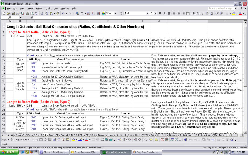
Length Ratio Outputs for Sailboat Characteristics
-
Length Beam Ratio, L/Bmax,
dimensionless. High values
indicate large form stability, faster speeds (if light boat) and
larger interior volume. Low values indicate gentler motions and
normally safer blue water performance.
-
Waterline Length - Waterline Beam Ratio,
LWL/BWL, dimensionless
-
Overhang Ratio, OR = LOD/LWL, dimensionless
-
Draft Ratio Outputs for Sailboats
-
Length to Draft Ratio, LWL/Draft,
dimensionless
-
Length to Canoe Draft Ratio, LWL/DraftC
dimensionless
-
Beam to Draft Ratio, BWL/Draft, dimensionless
-
Beam to Canoe Draft Ratio, BWL/DraftC,
dimensionless
-
Freeboard Ratio Outputs for Sailboat Characteristics
-
Forward Freeboard Ratio, FFR = FFWD/LWL,
dimensionless
-
Forward Ratio, FR = FFWD/FAFT,
dimensionless
-
Speed Parameters for Sailboats
-
Operational Speed Length Ratio, SLR = VOP/LWL1/2
-
Recommended Operational Speed, VFN
= Fn(g x LWL)1/2/1.689
based on an optimum Froude Number equal to 0.35, knots
-
Recommended Optimum Speed Length Ratio, SLRFN
= VFN/LWL1/2
-
Maximum Speed Length Ratio based on DLR, SLR1
= 8.26 / DLR0.311
-
Maximum Speed Length Ratio based on Bottom Exit
Angle, SLR2
-
Maximum Speed Based on DLR & Bottom Exit Angle,
Vmax
knots, this speed based the the lesser of SLR1 and SLR2.
-
Displacement Hull Speed, VHULL
= 1.34 x LWL1/2 knots,
maximum speed for a normal displacement hulls.
This value is based on a speed length ratio (SLR) equal to 1.34. At
this speed length ratio the length of the wave generated by the hull
is equal to the length of the hull. However, this barrier speed does
not apply to all sailboat hulls. Hulls that are very light with flat
exit angles and wide beams may exceed this value and go into
semi-displacement or semi-planing or even planing mode. Also hulls
that are very narrow and light, like racing catamarans, can exceed
this speed.
-
Velocity Ratio, VMAX/
VHULL = 1.88 LWL1/2SA1/3/D1/4)/
VHULL based on length, sail
area, displacement and hull speed
-
Maximum Speed based on Velocity Ratio, knots,
where VMAX =
(VMAX/ VHULL
) VHULL
maximum speed
based on velocity ratio
-
Sail Boat Speed Maximum Expected based on all
above, knots, where VME
equals the greater of Vmax
and VMAX
-
Recommended Optimum Speed Length Ratio, SLRFN
= VFN/LWL1/2
-
Displacement and Length
Parameters for Sailing Vessels
-
Displacement Length Ratio, DLR = (D/2240)/(LWL/100)3,
long tons / cubic feet. Generally the
vessel with the lower value will be the faster vessel. But ideal
values depend on the speed length ratio
range that the vessel is operating at.
Design lanes for
optimal DLRs as
a function of speed length ratio are given in
the references.
-
Length Displacement Ratio, LDR = LWL / V1/3
dimensionless
-
Prismatic Coefficient for Sail Boats
-
Various Parameters Involving Sails
-
Sail Area Displacement Ratio, SADR = SA / V2/3
dimensionless. The SADR is
a measure of the power available to push the load (the
displacement). Generally, the higher the value the faster the boat,
provided the boat is stiff enough to handle the larger sail areas.
-
Sail Area Wetted Surface Ratio, SA/WS,
dimensionless.
This ratio is an indicator sail boat performance
in light and medium air.
-
Sail Area Lateral Plane Ratio, (ALP/SA)100
percentage
-
Ballast Ratio for Sailing Vessels
-
Ballast Ratio,
where BR =
WB/D
dimensionless. This is an indicator of
stability, but it is not a very accurate one. This is because this
ratio does not differentiate between bulb ballast at the bottom of
the keel and ballast in the fin keel or hull. Since the location of
the ballast is not taken into consideration only boats with similar
ballast arrangements should be considered.
-
Sailboat Lead Characteristics (check for acceptable
values)
-
Stability Outputs for Sailing Craft, Sheet 1
-
Righting Arm at 20 degrees (estimated), GZ20
= (BWL/T)2/14.84, feet
-
Righting Arm at 30 degrees (estimated), GZ30
= (BWL/T)2/11.00, feet
-
Righting Arm at 30 degrees (estimated), GZ'30
= 0.03LWL4/D,
feet
-
Righting Moment at 30 degrees (estimated), RM30
= the larger of GZ30D
or GZ'30D,
foot pounds
-
Screening Stability Value, used for
calculating capsize screening value, SSV = (BMAX/3.28084)2/(BR
x (DraftC/3.28084) x
(V/3.280843)1/3)
-
Angle of Vanishing Stability, AVS = 110 +
(400/(SSV-10)), degrees
-
Stability Outputs for Sailing Craft, Sheet 2
-
Capsize Risk Factor (or Capsize Screening Factor),
where
CSF = BOA / V1/3
dimensionless. This
parameter is an indication of a vessel's ability to resist capsizing
in a violent storm. This factor is
concerned with dynamic stability in which weight and beam are
predominate factors.
-
Roll Acceleration, AROLL
= 2p(T)2Radius(qROLLp/180)/32.2
-
Stability Index, SI = T /(BOA x 0.3048)
-
Sail Boat Stiffness Factors, Sheet 1
-
Righting Moment at 20 degrees, RM20
= GZ20D,
foot pounds
-
Heeling Moment at 20 degrees, HM20
= SA x HA x cos2(20
degrees)xP foot pounds, where P is 1 pound per square foot wind
pressure
-
Wind Pressure Coefficient (Type 1), WPC = RM20/HM20
dimensionless
-
Righting Moment at 20 degrees (Type 2), RM'20
= DGM sin(20 degrees)foot pounds, more
approximate than Type 1
-
Wind Pressure Coefficient (Type 2), WPC = RM'20/HM20
dimensionless
-
Sail Boat Stiffness Factors, Sheet
2
-
Upright Heeling Moment, UHM = SA x HA x P,
where P is wind pressure at1 pound per square foot, results in foot
pounds
-
Heeling Moment for 1 Degree, HM1
Degree = D x GM x Sin(1
degree) results in foot pounds
-
Dellenbaugh Angle, DA
= UHM / HM1 Degree
-
Sailing Vessel Comfort Factors
-
Roll Period, seconds, evaluate period input
value with target values that are presented in this section
-
Comfort Ratio, CR = D
/ (0.65 x (0.7xLWL + 0.30xLOA) x Bmax1.333).
This term was developed by yacht designer Ted Brewer.
Large numerical values
of this parameter indicate a
boat with a smoother,
steadier and more comfortable
motion in a seaway. Therefore the CR
parameter favors heavy
sail boats with lots
of overhang and a
narrow beam. Since these factors
slow down a boats response in heavy weather.
-
Waterplane Loading, WPL = (D/2240)/AWP,
this is a heave factor comfort check
-
Maximum Recommended Waterplane Loading, where
WPLR = a x (D/2240)2
+ b x (D/2240) + c
-
Factor of Safety on Waterplane Loading, FSWPL
= WPL / WPLR values
less than one are acceptable
-
Informational Sheets
-
Figures Sheet for Sailing Vessel Spreadsheet, one sheet
-
References
and Notes, one sheet
-
Instructions,
1 sheet
-
Use
Terms, 2 sheets
-
Formulas
(these sheets are for interpolations and extrapolations of target
data, they are normally not included with printed output) 5 sheets.
Recommended
Reading:
Books
-
Reference B-A: Arthur Edmunds,
Designing Power & Sail, page 193, 1998, Bristol Fashion
Publications, Harrisburg, PA.
-
Reference B-B: SNAME, Principles of
Naval Architecture, Volumes I and II, 1988, Society of Naval
Architects & Marine Engineers, Jersey City, NJ
-
Reference B-C: Dave Gerr, Propeller
Handbook, International Marine, 1989, Camden, Maine.
-
Reference B-D: C. A. Marchaj,
Seaworthiness, the Forgotten Factor, Chapter 4 - Boat Motions in a
Seaway, 1986, International Marine, Camden, Maine.
-
Reference B-E: Edward M. Brady, Marine
Salvage Operations, Cornell Maritime Press, 1960, Cambridge,
Maryland.
-
Reference B-F: Dave Gerr, Nature of
Boats, International Marine, 1995, Camden, Maine.
-
Reference B-G: Howard I. Chapelle,
Yacht Designing and Planning, 1971, W. W. Norton & Company, Inc.,
New York, NY.
-
Reference B-H: Norman L. Skene and Francis
S. Kinney, Skene's Elements of Yacht Design, 1973, Dodd, Mead &
Company, Inc., New York, NY.
-
Reference B-I: Juan Baader, The Sailing
Yacht, Second Edition, 1979, W. W. Norton & Company, Inc., New York,
NY.
-
Reference B-J: Lars Larsson and Rolf E.
Eliasson, Principles of Yacht Design, Second Edition, 2000,
International Marine, Camden, Maine.
-
Reference B-K: Pierre Guttelle, The
Design of Sailing Yachts, 1984, International Marine Publishing
Company, Camden, Maine.
-
Reference B-L: Robert G. Henry & Richards
T. Miller, Sailing Yacht Design, 1965, Cornell Maritime Press,
Inc., Cambridge, Maryland.
-
Reference B-M: K. Adlard Coles & Peter
Bruce (editors), Adlard Coles' Heavy Weather Sailing, 30th
edition, Chapter 2 Sailing Yachts in Large Breaking Waves, pages 11-23,
International Marine, Camden, Maine.
-
Reference B-N: C. A. Marchaj, Sailing
Theory and Practice, 1964, Dodd, Mead & Company, New York, New York.
-
Reference B-O: C. A. Marchaj,
Aero-Hydrodynamics of Sailing, 1979, Dodd, Mead & Company, New York,
New York.
-
Reference B-P: Douglas H. C. Birt,
Sailing Yacht Design, 1951, Robert Ross & Co. Limited, Southampton,
UK.
-
Reference B-Q: Andrew G. Hammitt,
Technical Yacht Design, 1975, Van Nostrand Reinhold Company, New
York, New York.
-
Reference B-R: D. Phillips-Birt, The
Naval Architecture of Small Craft, 1957, Hutchinson & Company,
London, UK.
-
Papers
-
Reference P-A: Robert G. Henry and
Richards T. Miller, Sailing Yacht Design - An Appreciation of a Fine
Art, pages 425-490, SNAME Transactions, Volume 71, 1963 issue,
Society of Naval Architects & Marine Engineers, Paramus, NJ.
-
Reference P-B: Richards T. Miller and Karl
L. Kirkman, Sailing Yacht Design - A New Appreciation of a Fine Art,
pages 187-237, SNAME Transactions, Volume 98, 1990 issue, Society of
Naval Architects & Marine Engineers, Paramus, NJ.
-
Articles
-
Reference A-A: Ted Brewer, Is Your Boat
Stable?, http://www.boatus.com/goodoldboat/stability.htm, Article
from Good Old Boat magazine: Volume 3, Number 2, March/April 2000.
-
Reference A-B: Ted Brewer, Brewer By
the Numbers, www.boatus.com/goodoldboat/brewerformulas.htm, Article
from Good Old Boat magazine: Volume 3, Number 2, March/April 2000.
-
Reference A-C: Roger Marshall, Design
By the Numbers, Motor Boating & Sailing magazine: September 1981.
-
Reference A-D: Roger Marshall, Design
Calculatons, The Design Process Part III, Article from Boatbuilder
Magazine, November/December 2004.
-
Web Sites
-
Reference W-A: John Holtrup, Several
articles including: "Design Basics," Fuzzy Logic," "Estimating
Stability," "Plots from Data Base,"
"Dynamic Stability," and "Best Offshore Cruising Boats" -
updated 20 June 2000,"
www.johnsboatstuff.com/technica.htm.
-
Reference W-B: Michael Kasten, "Sail
Area Ratios," http://www.kastenmarine.com/sail_area_ratios.pdf,
2001.
-
Reference W-C: Dan Pfeiffer, "Sailboat
Design Ratios," http://dan.pfeiffer.net/boat/ratios, 2003.
-
Reference W-D: SailingUSA.info, "Angle
of Vanishing Stability," http://www.sailingusa.info/cal_avs.htm and
formulas.htm, 2001.
-
Reference W-E: SailingUSA.info, "Keelboat
Course - Design & Stability,"
http://www.sailingusa.info/design_winds.htm, 1999 - 2002.
Terms:
Prior to purchase, read our
End User License Terms.
Important Notice to European Union Buyers:
Due to changes in international law, we
no longer accept purchases from any individuals located
within an EU country. However, businesses located
within the EU are allowed to make purchases, provided that they make
the VAT payments for any imported items purchased electronically.
These EU businesses must specify their VAT number in the memo
section on the Paypal payment pages. These changes are
effective as of July 1, 2008, and were modified for EU businesses on
April 9, 2010.
Download Now: click the following hyperlink to pay $50 fee and then
immediately download the zip file containing the template.
Minimum System Requirements: Windows 95/98/NT/2000/XP/Vista/Windows7
Sample:
A sample of an output page is shown below.
|