This is the initialization
value, feet.
The Maximum Available Righting Arm in this region is:
Angle Corresponding to this Maximum Righting Arm, degrees
Determine Limiting Angle, as per 46 CFR 173.095
(c)(2)
Limiting Angle, the least of 40 degrees, Angle of Maximum
Righting Arm and Downflooding Angle.
Determine Intercept (or Equilibrium) Angle Between Heeling
Arm Curve & Righting Arm Curve,
as per 46 CFR 173.095 (c)(1) and (2)
Initial Angle of Range needed for iterations below,
degrees.
A cubic spline is used to represent the end conditions.
The above function is redefined below in terms of a
cubic interpolation function.
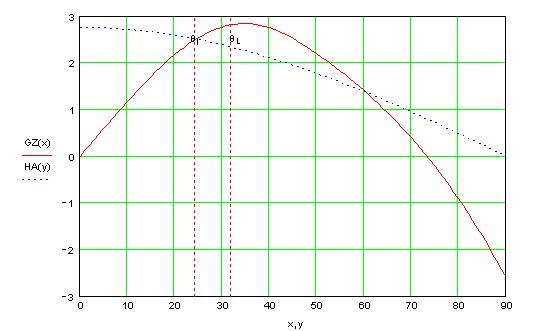
This function is graphed on the last page of this analysis.
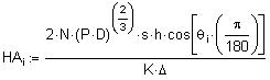
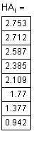
Calculations for Heeling
Arm Curve, as per Part 46 CFR 173.095 (d)
In this section the Heeling Arm Curve is calculated
through formula at right.
The formula for representing HA (heeling arm) as a function
of theda (heel angle) is derived as follows:
A cubic spline is used to represent the end conditions.
The above function is redefined below in terms of a cubic interpolation function.
This function is also graphed on the last page of this
analysis.
Determine Angle of Maximum Righting Arm,
as per 173.095(c)(2)(i)
Determining Maximum Righting Arm and its Corresponding
Angle
The Angle corresponding to maximum righting arm is obtained from the following
iterative process:
or Curve of Statical Stability
Summary of Important Inputs
Summary of Calculated Results
Downflooding
Angle, degrees
Residual Area Required Under RA Curve, feet·deg
Residual Area Available Under RA Curve, foot·deg
Results of this analysis, satisfactory only if equal
to one.
Vertical Center of Gravity, feet
Iteration Fineness, fractions
of a degree
Iteration Values, first value of range important because
of multiple intercepts possible for some cases, degrees.
Tolerance Allowed on GZ
Difference, feet
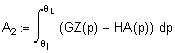
Check Equilibrium Angle to see if Less than Downflooding
Angle, per 46 CFR 173.095 (c)(1)
Check Energy to Limiting Angle, as per 46 CFR 173.095
(c)(2)
Calculate Area from Intercept Angle up to Limiting Angle
Check if meets Minimum Residual Moment Area requirements
Graph of Righting Arm Curve
Filename of the calculations that are contained here.
Vertical Center of Gravity, feet, above Baseline. The
is the same VCG (or KG) value that was used for constructing
the "Cross Curves of Stability." This value
facilitates fast cross checking with the other vessel
data.
Vessel Draft, feet. When INPUT =1 put in the mean draft
for the condition under evaluation. When INPUT=2 it
usually means the level draft is being evaluated.
Otherwise it is the LCF draft.
Downflooding Angle, based on the above draft and the
vessel's geometry. Part 46 CFR 173.095 (e) requires
the location where the hull does not close automatically.
Condition Inputs from Hydrostatics Program or Curves
of Form & Cross Curves of Stability
Input Righting Arms are below. No free surface effects are included
in this data
.
Vessel Displacement, long tons.
Keel to Metacenter for the Transverse Direction, feet,
this value obtained at the same time as the above displacement
for the level trim case. Where KMT = VCB + BMT.
Towline Pull, Dynamic Criterion, VCG Check, as per 46 CFR 173.095(c) - (f)
This analysis is based on the dynamic requirements contained
in 46 CFR 173.095 (c) through (f). These requirements
are an option to the static requirements stated by
46 CFR 173.095 (b). This analysis was prepared in
a Windows 95 operating system (or later version) with
MathCAD version 6 (or later version).
Vertical Center of Gravity, feet, above the Baseline
is positive. This value should already include the
free surface correction.
General Inputs for Vessel
TYPE =1 when a specific VCG is being checked. TYPE=2
when seeking the maximum allowable value for this criterion.
In a TYPE 2 analysis this VCG value is ITERATED to
obtain
the highest possible value that meets all this
criterion's requirements.
Vessel Particulars,
LBP x Beam
x Depth
Minimum Residual Moment Area Required, in English units
of foot·degrees
Formula Constant for English units
Metacentric Height Calculation
Available Metacentric Height, feet
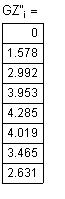
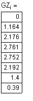
Calculations for Righting Arm Curve
In this formula a correction for VCG0 is made to the Righting Arm Curve.
The last column of this table shows Corrected Righting
Arms for VCG
The formula for representing GZ (righting arm) as a
function of theda (heel angle) is derived as follows:
Longitudinal Center of Gravity, feet, aft of Midships
is positive. For the level trim case this equals the
LCB value and it is obtained at the same time as the
displacement above.
If Input = 1 data for this condition is directly from
a hydrostatics program, if Input =2 data are from the
"Curves of Form" and the "Cross Curves
of Stability."
Vessel Inputs for Towing as
Defined by 46 CFR 173.095 (b)
fraction applicable to Z-Drive Tugs, value from Static
Requirements.
Shaft Power, per shaft, horsepower
Maximum Ve
rtical Distance from propeller shaft centerline to towing
bitts, feet
The procedures, techniques and presentation
contained on these pages are copyrighted. Only purchasers of the template may utilize them,
any other use is strictly prohibited.